CYBT-263065-EVAL
AIROC™ CYW20820 Bluetooth® & Bluetooth® LE Module Evaluation Kit (CYBT-263065-EVAL)
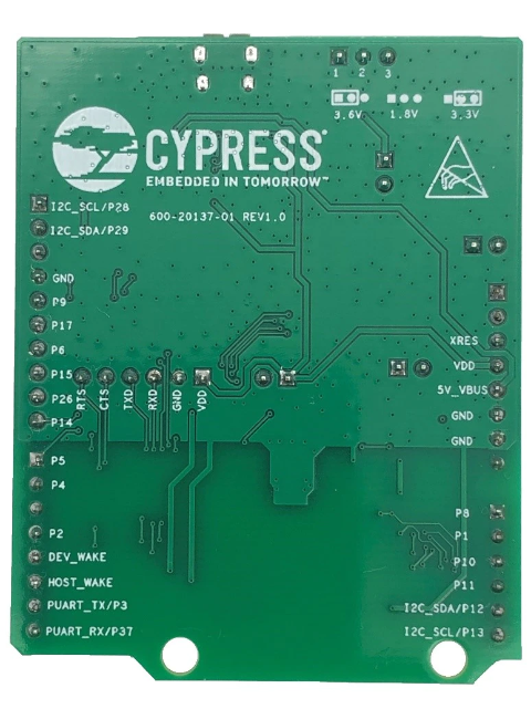
The Infineon AIROC™ CYBT-263065-EVAL Bluetooth® & Bluetooth® LE 5.4 Module Evaluation Kit enables evaluation, prototyping, and development of a wide array of IoT applications using the AIROC™ CYBT-263065-02 module. The AIROC™ CYBT-263065-02 Bluetooth® Module is globally certified, and has an external antenna interface with a -u.FL connector, rapidly reducing the time-to-market.
The Infineon AIROC™ CYBT-263065-EVAL Evaluation Kit is supported in the AIROC™ Bluetooth® SDK v3.2 or later within ModusToolbox™ Software and Tools with many code examples for various use cases. To learn more about ModusToolbox™ and download the latest version of the Bluetooth® SDK, please visit the Bluetooth® SDK community page.
AIROC™ CYBT-263065-EVAL Bluetooth® & Bluetooth® LE Module Evaluation Kit features:
- An evaluation board that can support various Bluetooth protocols including
- Generic Access Profile (GAP)
- Generic Attribute Profile (GATT)
- Security Manager Protocol (SMP)
- Radio Frequency Communication protocol (RFCOMM)
- Service Discovery Protocol (SDP)
- BLE Mesh protocol
- Eval board with integrated serial flash
- Input/output interfaces for communications and programming
- Various sensors - light sensor, thermistor and LEDs
- External headers for debugging and connectivity
- Interfaces to USB power or to a coin cell
- PCB Antenna and PA/LNA
- 24MHz crystal oscillator
- 1 X Module Arduino Evaluation Board (CYBT-263065-EVAL) with on-board AIROC™ Module (CYBT-263065-02)
- 1 X USB Cable for USB – UART programming
- Convenient user buttons
- Bluetooth and Bluetooth module

1) Configure the evaluation board headers/switches to the desired settings.
2) Connect the evaluation board to a PC via a USB cable.
3) Open ModusToolbox, and develop, program, and test your application.
Note: Recover the CYBT-263065-EVAL board before programming.
The Arduino-compatible headers (J3/J4/J6/J7) are optional connections, which provide additional I/O connections to the module and allow for other Arduino shields to be used during development.
SW1: Reset switch routed to the XRES connection on the module.
SW2: Recover switch routed to the UART_CTS connection on the module.
SW3: User-defined switch routed to the P0 connection on the module via J9.
SW4: Switch connecting HCI UART connections on the module to the host via USB.
SW5: Switch connecting PUART connections on the module to the host via USB.
J1: Connection for an external interface for direct HCI UART communication.
J2: Used for module power supply current measurement.
J3/J4/J6/J7: Arduino-compatible headers used with an Arduino-compatible shield.
J8: Configures the VDD voltage input to the module as shown in the following table:
| J8 Jumper Configuration | VDD Voltage Level |
| Short 1 & 2 | 3.0V |
| Open | 1.8V |
J9: Connects the P0 pad on the module to SW3.
J10: Connects the P26 pad on the module to LED D1.
J11: Module power supply selection from LDO or external connector.
The EZ-BT CYBT-263065-02 Module supports Bluetooth SIG Mesh, is qualified for the Bluetooth 5.4 speci¬fication and is certifi¬ed for the 2.4-GHz unlicensed frequency range in USA (FCC), Canada (ISED), Europe (CE), and Japan (MIC).


